IKEA · Beds
How to Assemble IKEA MALM Storage Bed
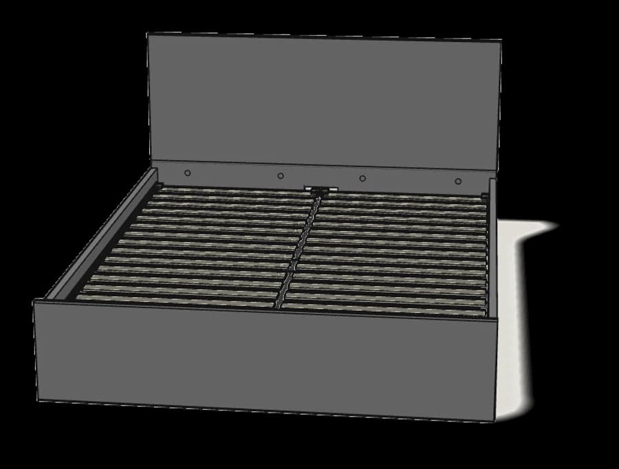
Step-by-step IKEA MALM storage bed assembly: 24 illustrated steps, an animated video, the hardware list and the tools you need — following the official instructions (AA-2055625-9).
- 24 illustrated steps
- 36 steps in the manual
- 3:26 video
- 168×211×100 cm
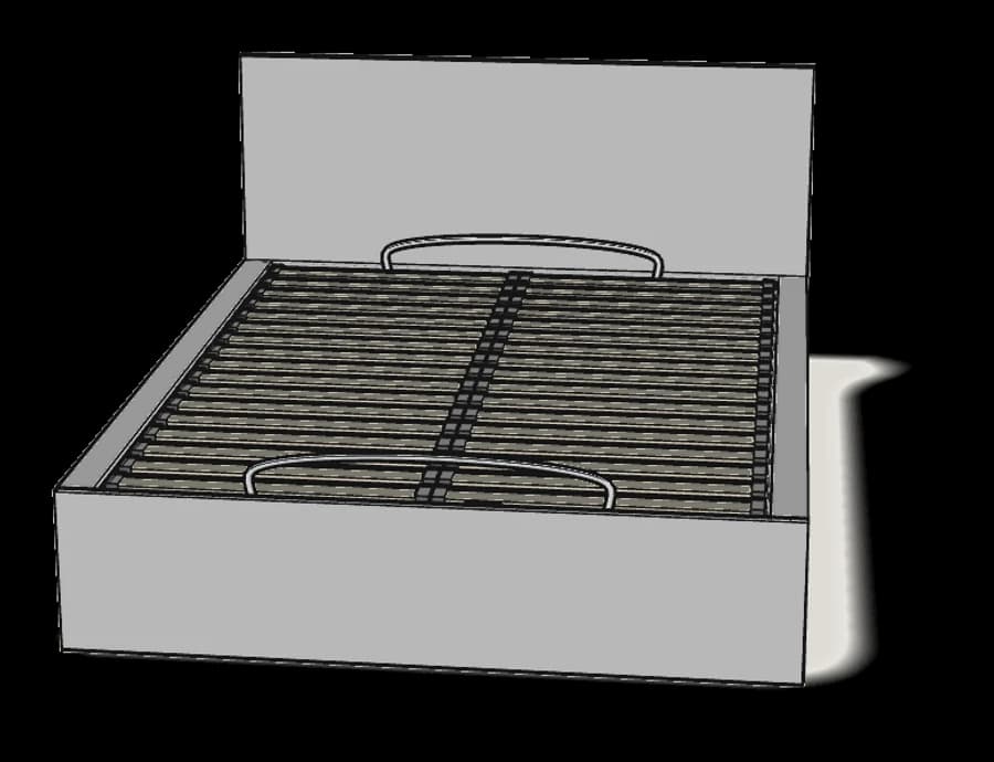
What you need
Tools
- Flat-head screwdriver
- Phillips screwdriver
- Allen key (included)
- Spanner (included)
You’ll need: a flat-head and a Phillips screwdriver.
Hardware in the box
| Part no. (as printed in the manual) | Qty |
|---|---|
| 123491 | 4× |
| 130618 | 8× |
| 114334 | 4× |
| 101367 | 5× |
| 101359 | 16× |
| 115311 | 8× |
| 114670 | 4× |
| 122998 | 4× |
| 114254 | 4× |
| 123851 | 4× |
| 123852 | 2× |
| 123849 | 2× |
| 124252 | 4× |
| 123850 | 4× |
| 109021 | 46× |
| 190018 | 4× |
| 123848 | 2× |
| 124584 | 6× |
| 158998 | 12× |
| 105107 | 2× |
| 115461 | 4× |
| 110440 | 2× |
| 157409 | 24× |
Step-by-step assembly
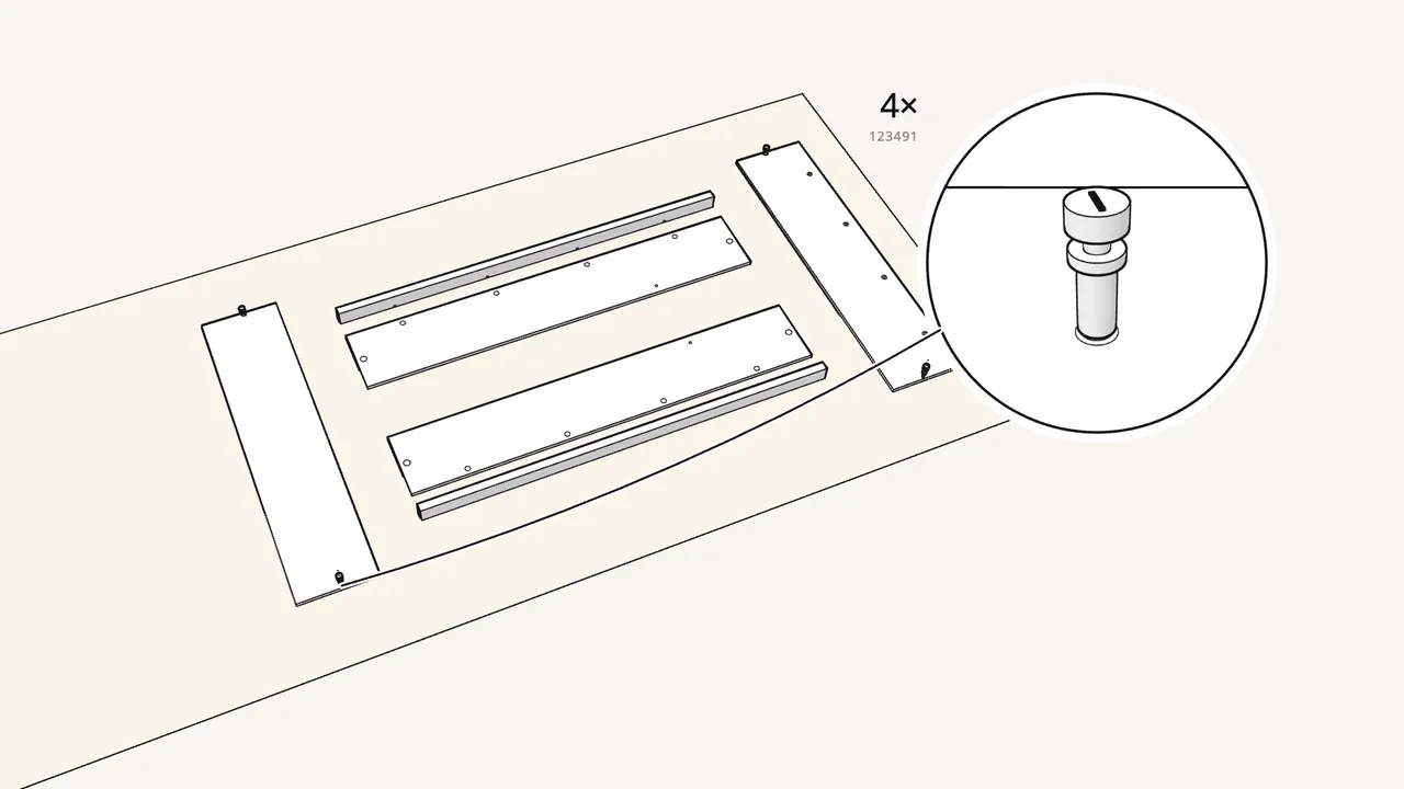
Step 1 · manual step 2
Screw 4 connector bolts (123491) into the head and foot panels.
Use the spanner (113453). Lay all panels on a rug first (step 1).
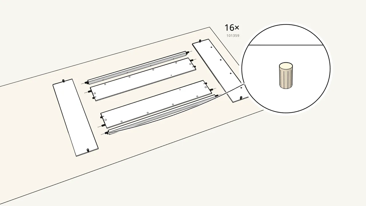
Step 2 · manual step 3
Push 16 dowels (101359) into the ends of the side panels and rails.
Use the short 101359 dowels here — the long 101367 ones come later.
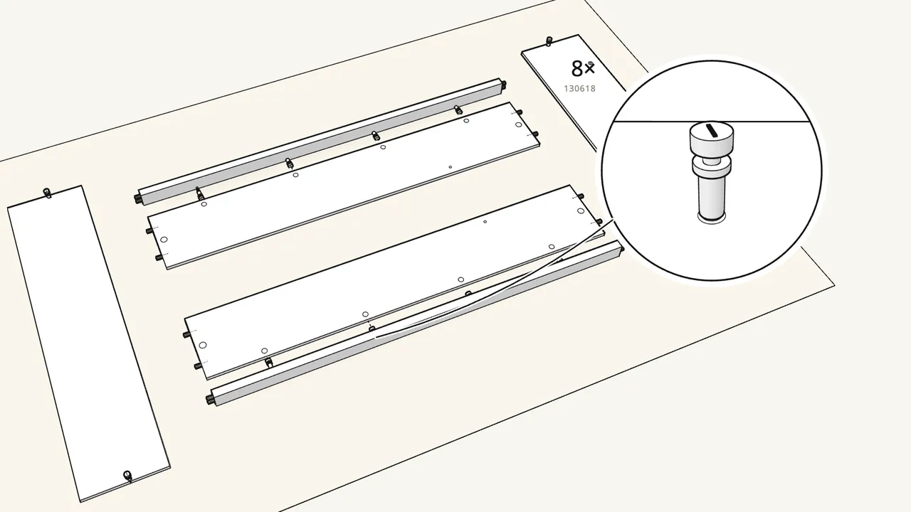
Step 3 · manual step 4
Screw 8 cam bolts (130618) into the two rails.
4 per rail, with the Phillips screwdriver.
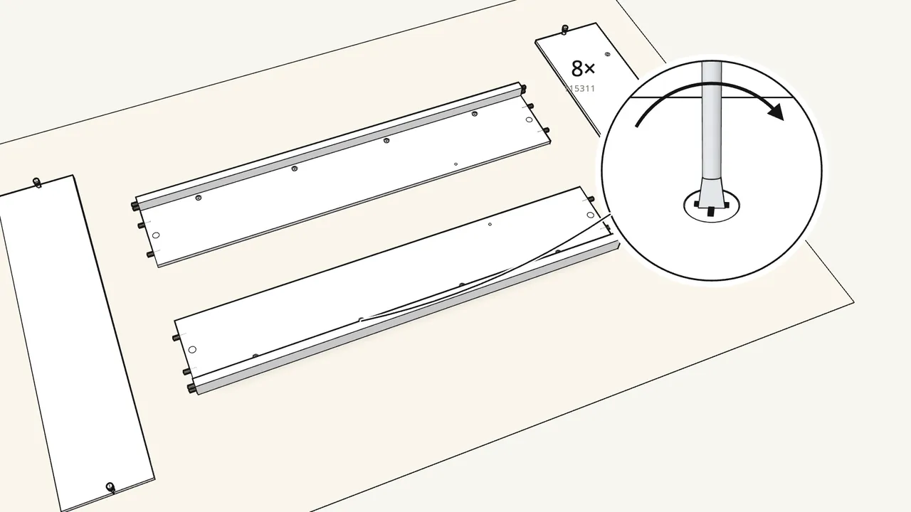
Step 4 · manual step 5–6
Fit a rail onto the top edge of each side panel.
Then insert 8 cam locks (115311) and turn them with the flat-head screwdriver.
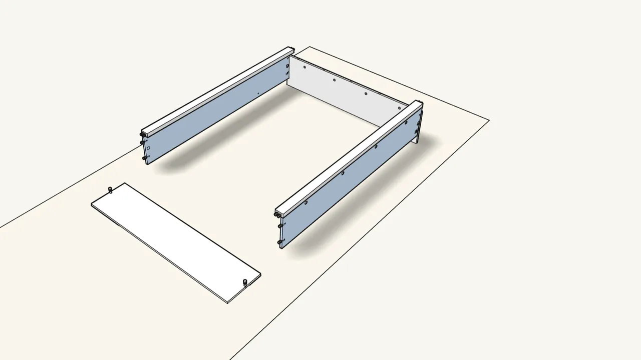
Step 5 · manual step 7
Stand the head panel up and join both side panels to it.
Put a cam lock (114670) in each side panel, then turn them with the Allen key (100049).
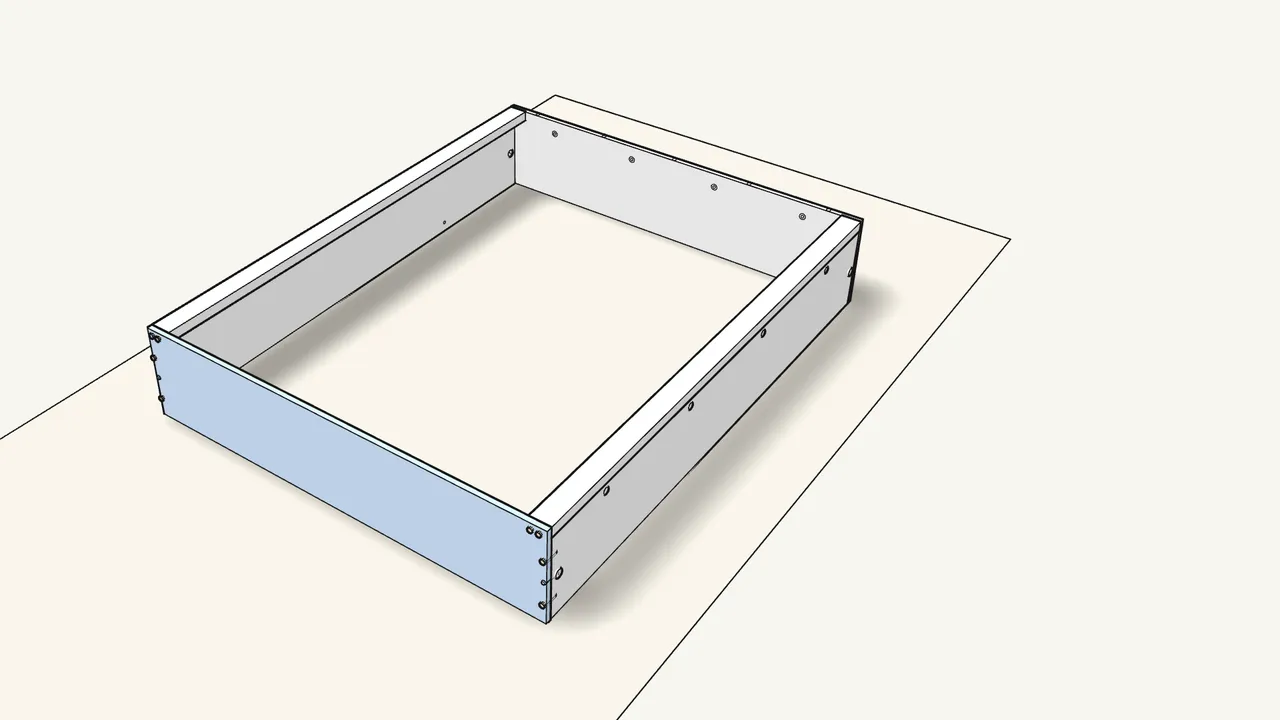
Step 6 · manual step 8
Fit the footboard the same way.
Two more cam locks (114670), turned with the Allen key.
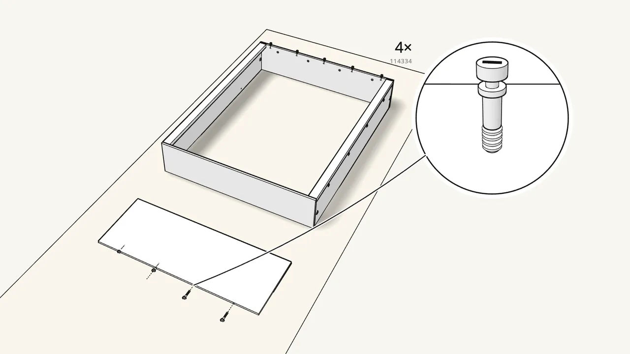
Step 7 · manual step 9–10
Push 5 long dowels (101367) into the head panel; fit 4 studs (114334).
The studs go into the bottom edge of the upper headboard — use the spanner, don’t sink them.
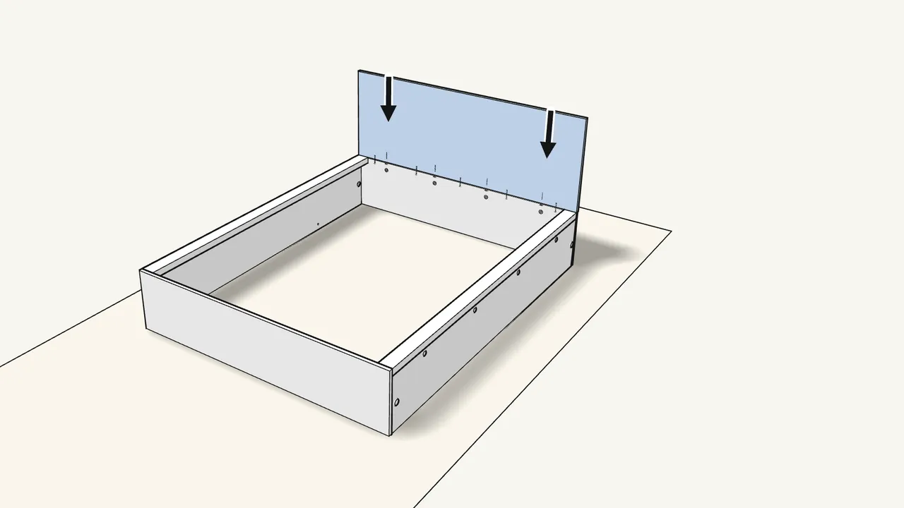
Step 8 · manual step 11
Lift the upper headboard onto the head panel.
The studs and dowels go into the holes in the top edge.
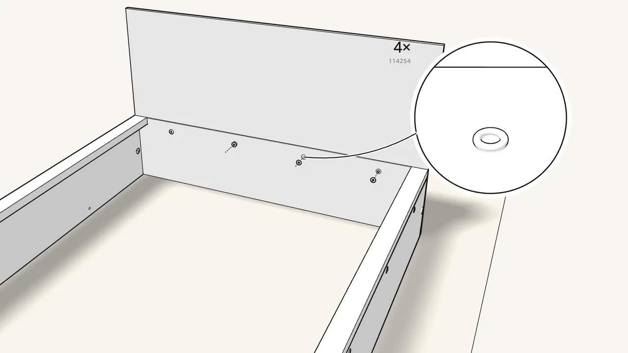
Step 9 · manual step 11
Fit 4 plastic inserts (122998), then tighten 4 nuts (114254).
Reach in through the round holes inside the head panel. Tighten with the spanner.
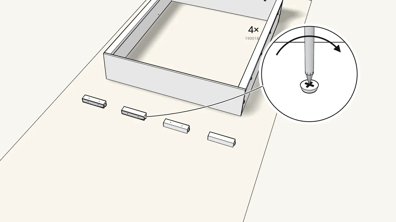
Step 10 · manual step 12
Screw an end piece (124252) onto each of the 4 supports (128895).
One screw (190018) each.
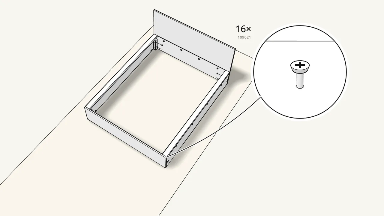
Step 11 · manual step 13
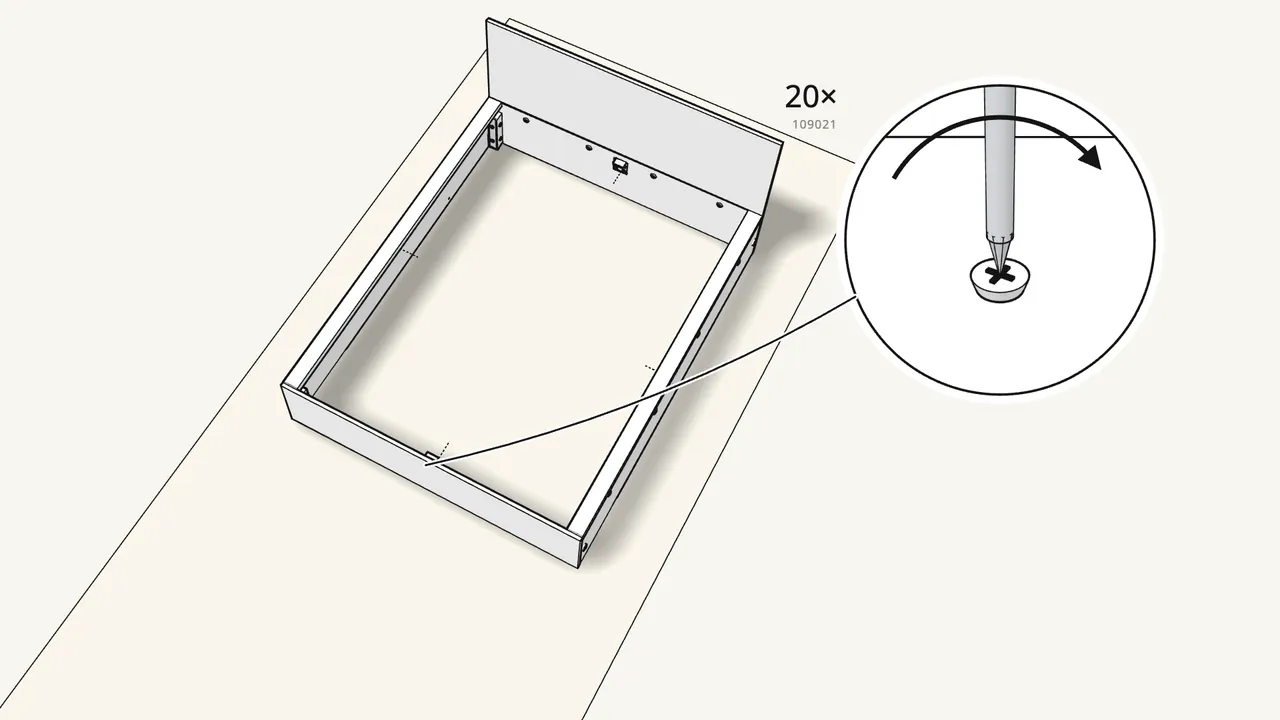
Screw a support into each inside corner of the frame.
16 screws (109021), 4 per support. The manual props the frame up on packaging first.
Step 12 · manual step 14–15
Screw on the 4 rests (124249) and the bracket (124389).
4 screws (109021) each. For the exact positions see the manual, steps 14–15.
Step 13 · manual step 16–18
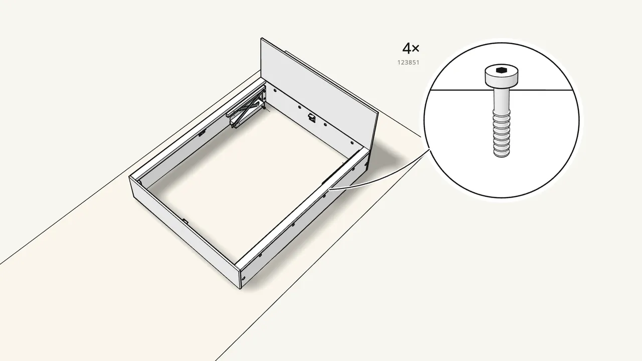
Fit the L and R lift mechanisms to the side panels.
First 2 connectors (123849). Then 2 bolts (123851) with sleeves (123850) per mechanism — check the L/R labels.
Step 14 · manual step 19
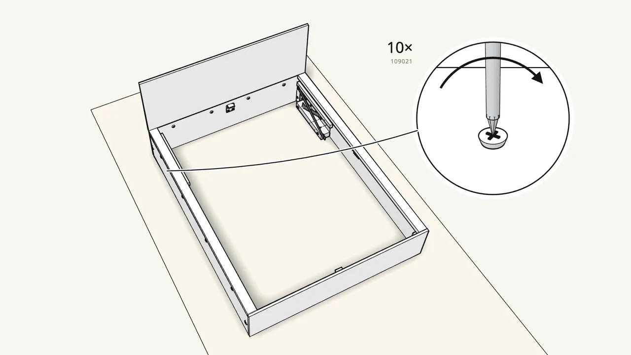
Screw both mechanisms to the side panels.
10 screws (109021), 5 per mechanism.
Step 15 · manual step 20–21
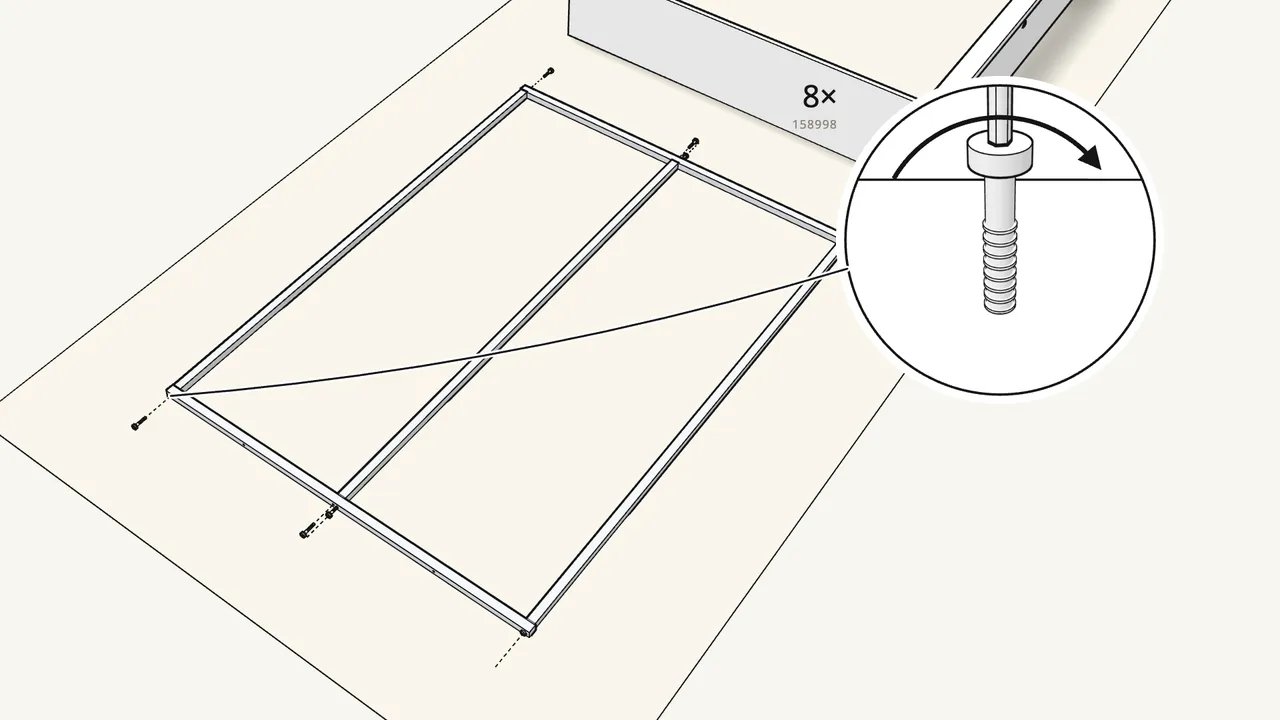
Join the steel frame profiles with 8 bolts (158998).
Use the Allen key 108490. Check which way the profiles face — see the manual, steps 20–21.
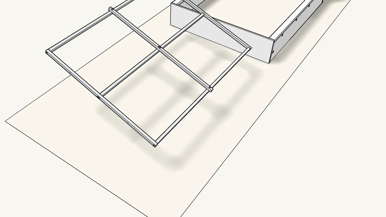
Step 16 · manual step 22
Bolt the cross bar across the middle, then turn the frame over.
4 bolts (158998).
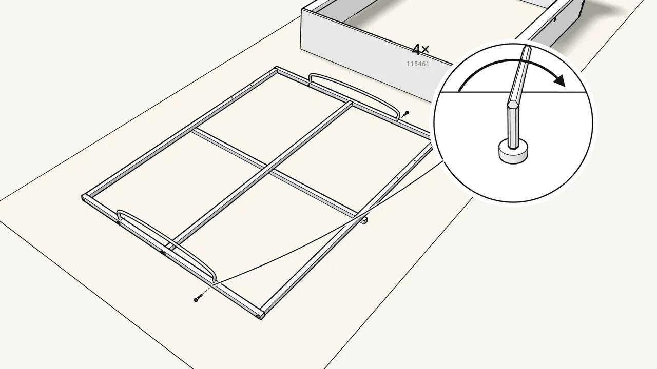
Step 17 · manual step 23
Fit the 2 U-shaped bars to the ends of the frame.
4 bolts (115461) with the Allen key 100001 — not the longer 105107.
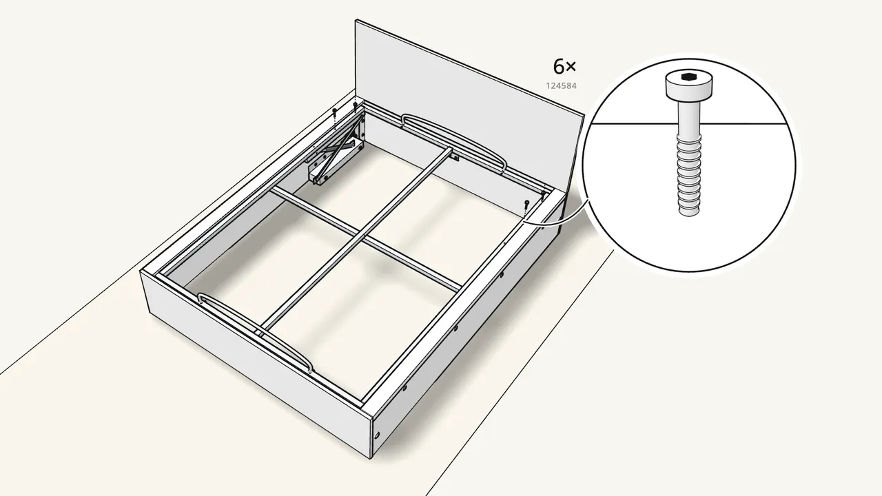
Step 18 · manual step 24
With two people, lay the frame onto the mechanisms.
Bolt it on with 6 bolts (124584) and the Allen key 108490.
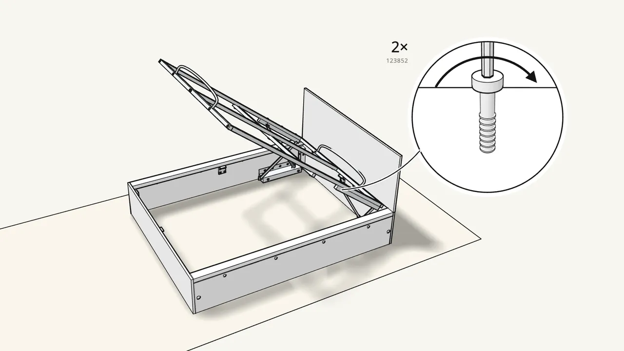
Step 19 · manual step 25–27
Raise the base. Fit 2 spacers (123848) and 2 bolts (123852).
Then tighten the mechanism bolts with the Allen key 100049 — see the manual, steps 25–27.
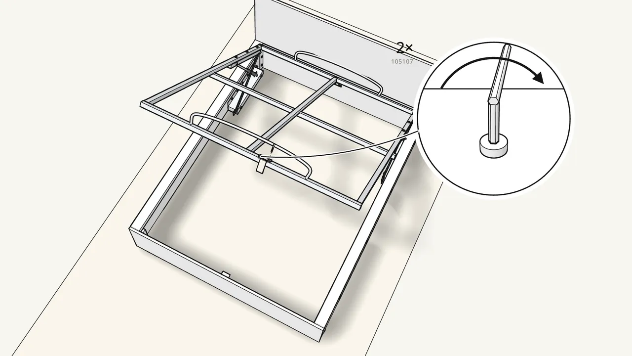
Step 20 · manual step 28
Fit the strap (124390) and latch plate (124573) at the foot end.
2 bolts (105107) and 2 bolts (110440) — see the manual, step 28.
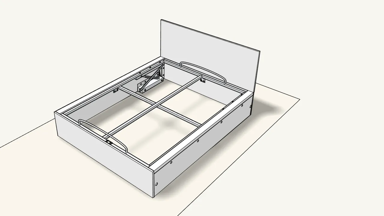
Step 21 · manual step 29–30
With two people, lower the base again.
Tuck the strap in at the foot end.
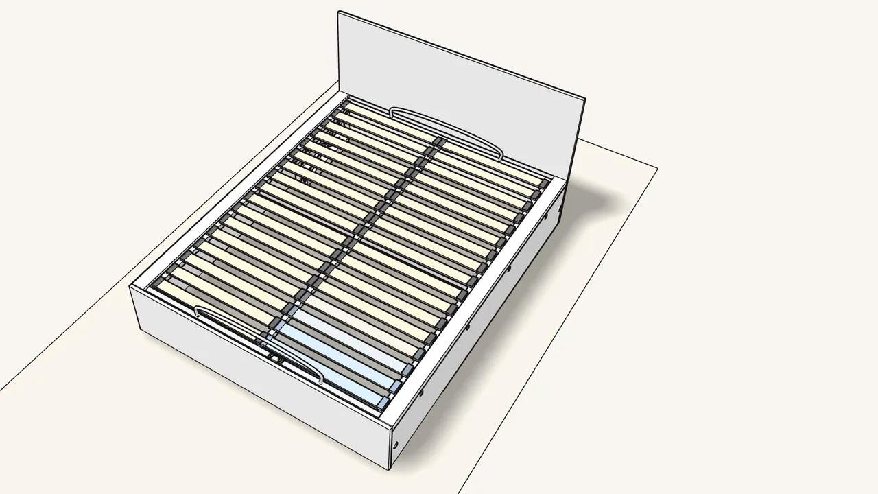
Step 22 · manual step 31–32
Clip a slat holder (124663) on each slat end, then lay in the slats.
The holders fit into the holes in the frame — one row each side of the centre profile.
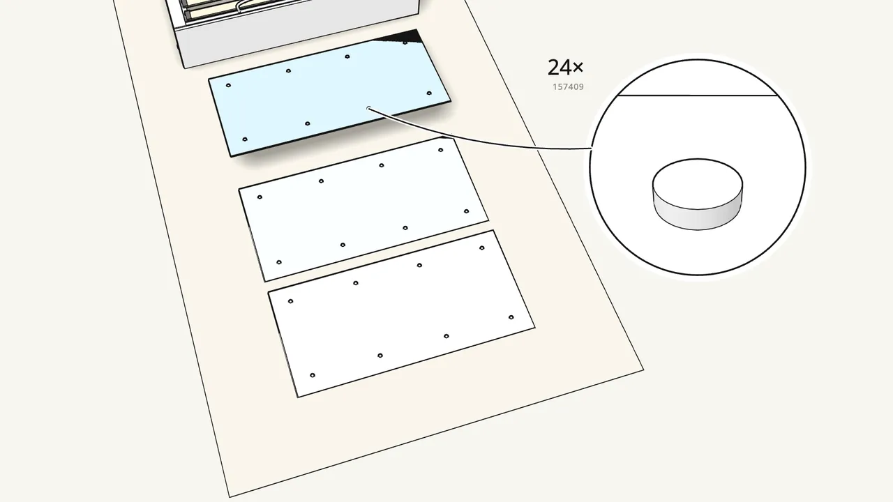
Step 23 · manual step 35
Stick 24 felt pads (157409) under the 3 bottom panels.
8 on each panel.
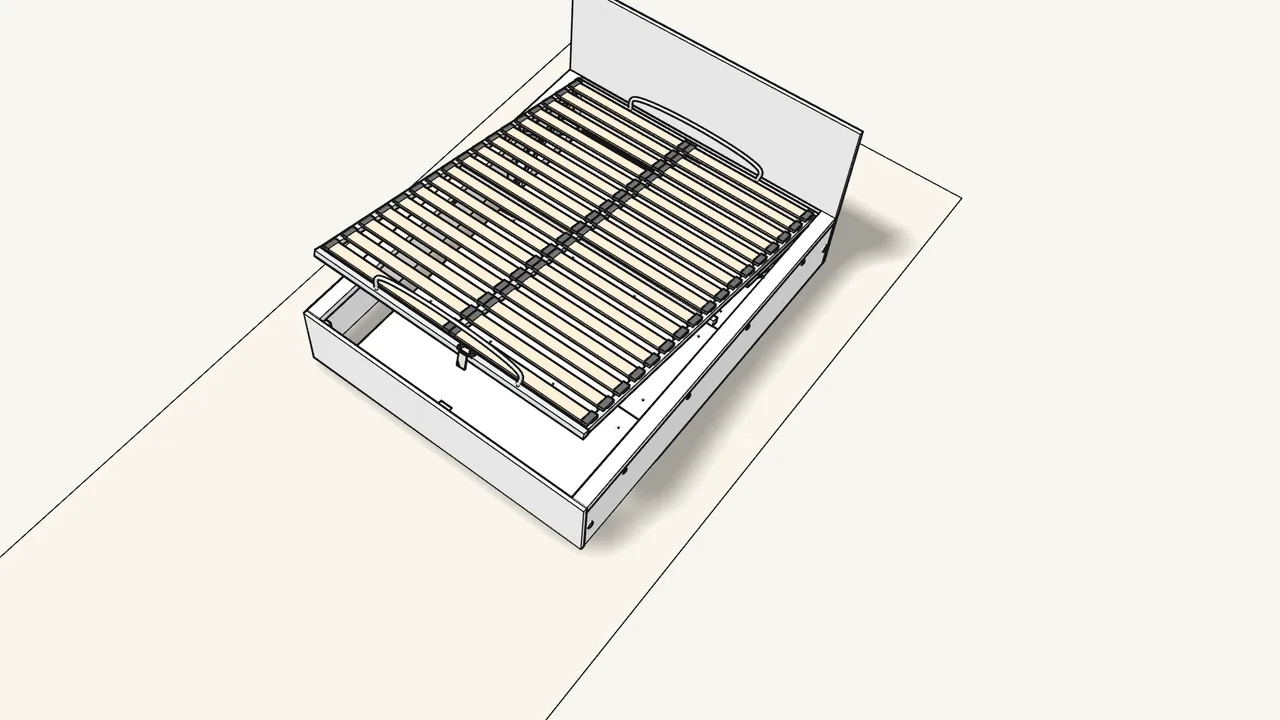
Step 24 · manual step 36
Lift the base and lay the 3 panels in the storage space.
Felt pads down. Then lower the base with the strap.
Tips & safety
- Only raise the base with the mattress on it. The manual (p. 32) marks lifting the empty base as wrong. Max mattress weight for Queen: 50 kg (p. 33).
- Keep children out of the storage space. Nobody should climb on the raised base or sit under it — see the warnings on pages 34 and 36.
Official instructions
This guide follows IKEA's official assembly instructions (AA-2055625-9). Keep the printed manual to hand — if anything differs, the manual is right.